I need a 137 MHz bandpass filter for my little NOAA weather satellite receiver, so like anything else, you can find what you want on the internet. So there is no need for another copy of a copy of an article, but I like to keep thoughts and information buzzing around in my head together at some place.
The first thing you should know is, that to build a band pass filter you need to analyse its characteristics. Therefore, you need some tool to analyse the frequency response and some source which can produce some good white noise.
The Noise Source
I got my inspiration for the noise source from Hans Van Ingelgoms, he describes how to use an RTL-SDR dongle and a noise source to measure the response of a 137Mhz filter for NOAA weather satellites.
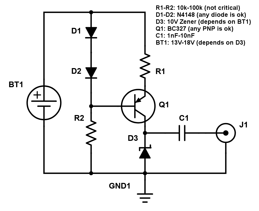
It is based on a Zener diode which produces a lot of noise when used in reverse. The transistor Q1 the resistors R1 and diodes D1 and D2 are working like a current source for the Zener diode D3, the capacitor C1 blocks away the DC part.
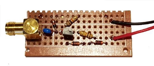
The ready soldered noise source on some perfboard. Not a beauty but it does its job. I get some good amount of noise when powered above 12V, so I use two 9V block batteries in series.
137MHz Band Pass Filter for NOAA Satellites
The original schematic for this filter I found on LNA4ALL posted by 9A4QV. It is a simple Butterworth Filter (Direct Coupled Resonator Bandpass Filter) made out of 5 capacitors and 2 inductors, so very easy to build. For the inductors I used some 0.8 mm isolated copper wire twisted 4 times around a 6 mm core.
To get a good estimation for the value of the self-made inductor, I recommend one of the following sites:
- RF Inductance Calculator for Single‑Layer Helical Round‑Wire Coils
- Solenoid Inductance Calculator
- Coil design and inductance calculator (This one calculates bigger values, so not sure how accurate it is.)
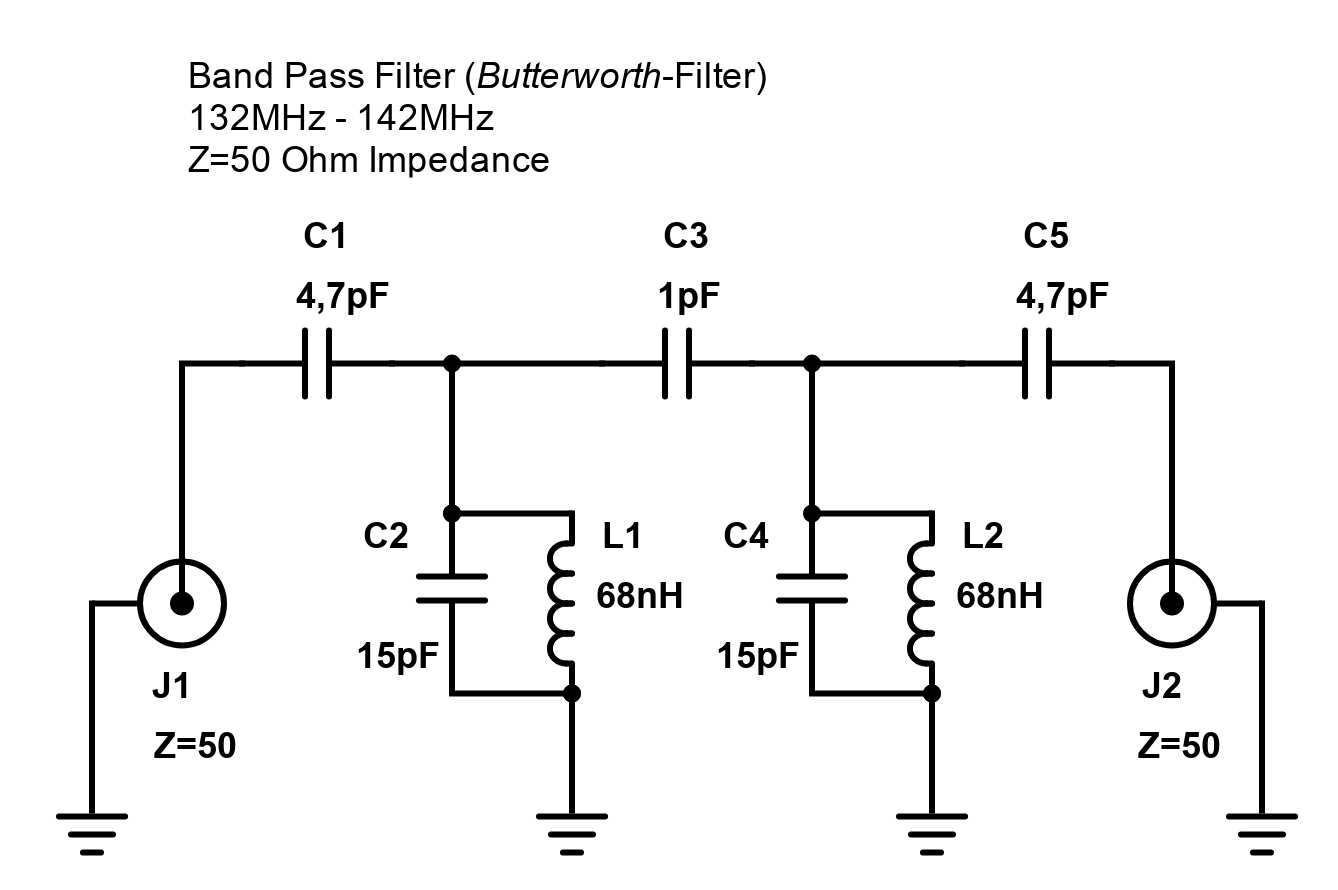
If you want to simulate this filter, have a look at the nice page with information about filters and electronics from Alexander C. Frank. Jump to the Direct Coupled Resonator Bandpass Filter Designer and use the following settings:
Center Frequency [MHz]: 137
Bandwidth [MHz]: 10
Passband Ripple [dB]: 0
Number of Resonators: 2
Impedance [Ω]: 50
Inductance: 68 nH use my value
After all parts are soldered together you need to adjust the coils until you reach the peak at 137MHz. Therefore, you can stretch the coils apart. But how can you see when you get a peak at 137MHz? Here comes the RTL-SDR dongle into the game. An RTL-SDR dongle combined with some nice and free software gives you a very useful Spectrum Analyser nearly for free. Tools like RTLSDR Scanner or QSpectrumAnalyzer will do the job.
At first check if your noise source produces a good amount of white noise. You can use spectrum analyser software like RTLSDR Scanner or QSpectrumAnalyzer for this job, or you can just use tools like SDR#, HDSDR or GQRX to check if you get enough noise.
I did it the following way:
- First I used SDR# and increased the gain step by step, as long until my noise source produces around 30dB of noise and wrote down the gain value.
- Then I used SDRRTL Scanner and set the gain to the value I wrote down and did a scan from 110MHz - 165MHz only with the noise source.
- Then I connected the filter between the noise source and the dongle and let the software scan again.
- Stretched the coils a little and analysed the output again, repeated this step until I got a good peak at 137MHz.
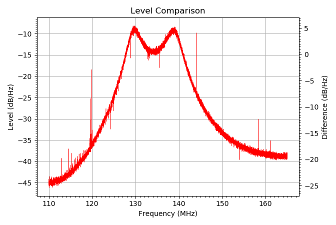
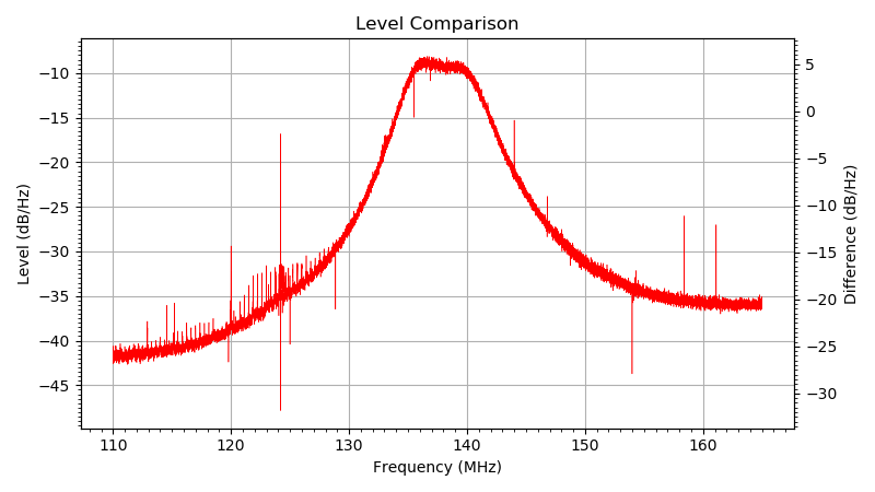
In the next picture you can see the output of the filter recorded with RTLSDR Scanner. It is not perfect, it has some over coupling but it is useable for my purposes.
The ready soldered filter with stretched coils and without any shielding between the input and output made on some perfboard.
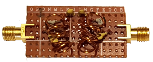
Next step is to put that filter into some housing to protect it against bad RF from its environment.
I cut and bend some sheet metal to get some kind of housing, and here it is.
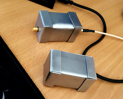
Second attempt of a filter with a different middle coupling capacitor, based on twisted isolated copper wires. I also shielded the two sides from each other. This filter seams to have just a bit of over coupling.
The second soldered board with its gimmick capacitor and the shield between the two sides.
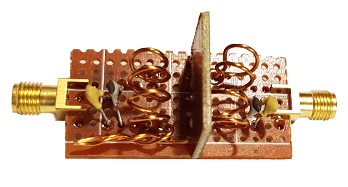
Have also a look on the video Practical RF Filter Design and Construction made by devttys0. He shows, that it is necessary to shield the input from the output side to avoid unwanted coupling between the coils at higher frequencies.
KiCad based PCB design of a 137 MHz Band-pass Filter.
Another approach with serialized capacitors: 137mhz-bandpass-filter-for-noaa-meteor-satellites


Comments powered by CComment