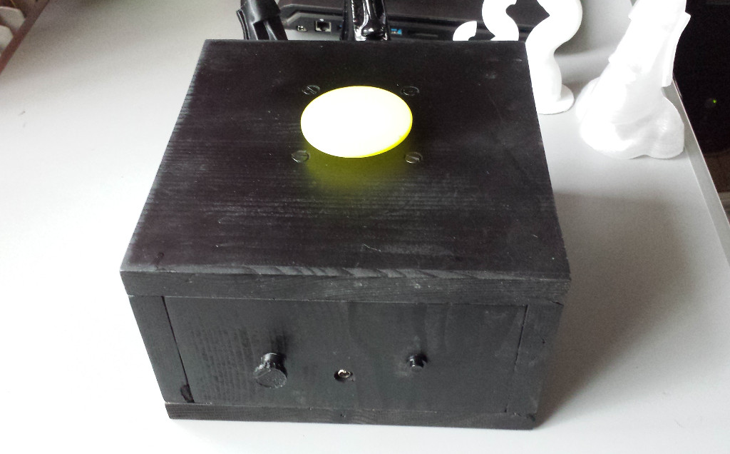
The rotating device is a small plattform where some small objects can be put onto and then they can be rotated clockwise or counter clockwise.
That's all this little fellow can do.
Hardware

To build this small device some componets are needed:
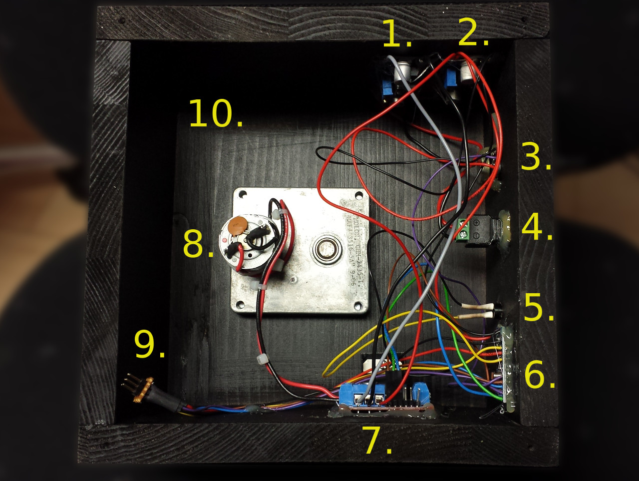
1.) Step-Up Converter
Create 20-24V out of the 12V power source. Only needed if the gear motor runs with 24V instead of 12V. In this project a XL6009 based step-down converter is used.
2.) Step-Down Converter
Create 5V out of the 12V power source. Only needed if the gear motor runs with 24V instead of 12V or if the Arduino and additional parts consume more than 200mA. In this project a LM2596 based step-down converter is used.
3.) 50k Ohm Potentiometer
Used to set the speed of the motor. The side pins are connected to vcc (5.0V) and ground (GND). The middle pin is connected to an ADC pin of the Arduino.
4.) 5.5 / 1.7 Female DC connector
Used to bring the power to the rotating device. Is connected to the input pin of the step-up and step-down converter.
5.) Push Button NO.
The push button is used to start the rotating, change the direction and to stop the motor.
6.) Arduino Pro Mini 5V
The Arduino reads the voltage of the potentiometer with the use of the ADC and sets the duty cylce of the pwm signal according to the voltage.
7.) L298N Dual H-Bridge Driver Modul
Drives the 24V gear motor. The 5.0V logic voltage is get from the step-down converter so the jumper has to be removed. This modul can be found everywhere for 1-2 € on the internet. But it is only usefull for a small motor with less power consumtion. If a 12V gear motor is used, and not much power consumpting elements are connected to the Arduino Mini, it is possible to generate the 5V directly on the L298N modul to power up itself and to power the Arduino Mini.
8.) 24V Gear Motor
The gear motor drives the rotating platform. This one is used for this project: http://www.pollin.de/shop/dt/Nzc1OTg2OTk-/Bauelemente_Bauteile/Motoren/DC_Getriebemotoren/Gleichstrom_Getriebemotor_CHM_2435_1.html
It is also possible to use a 12V gear motor, in that case the step-up converter is no more neccessary.
9.) 6Pin ISP Connector
This connector is wired to the Arduino Mini ISP pins. It is used to flash the firmware onto the Arduino.
10.) Wooden Box.
To hold all parts in place, a box is needed. For this small project the box is made of wood.
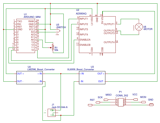
The following schematic is not complete but it shows how to connect the different parts together. Output1 and Output2 are used to connect the motor to the h-bridge. The connector P1 shows, that also an 2x3 header has to be connected to the Arduino Mini like shown, to be able to flash some data onto it.

The following picture shows how the different parts are mounted in the wooden box. I simply used hot glue to fix the parts.

Software
The software can be downloaded here: (comming soon)
It is not an Arduino based software. AVR Studio or a similar tools has to used to flash it to the ATmega328.
3D Printing
Only two 3d printed objects are needed. The first thing is the rotating platform which is connected to the gear motor. The second is the knob for the potentiometer.
The rotating platform can be found here: http://www.thingiverse.com/thing:1774080 and the knob here: http://www.thingiverse.com/thing:1774083


Comments powered by CComment